
The Bus Fault Injection Board allows the user to inject faults into a physical layer of a differential network (such as the CAN bus). The board can simulate errors: a wrong termination resistor, open/shorted CAN_H or CAN_L to Gnd/Vdd, disconnected Gnd or Vdd or Shield signal. The fault injector board is suitable for CAN, CAN FD, FlexRay, RS-485, and LIN buses.
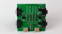
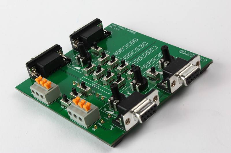
The Board has two sides – left and right. There are two D-SUB9F connectors wired 1:1 at each side. The switches for fault injection are placed between the sides. If all the switches are in “OK” position, there is no fault injected into the physical layer and left and right sides are connected correctly. This means all four D-SUB connectors are connected 1:1 and the board can be used for a normal interconnection of network devices.
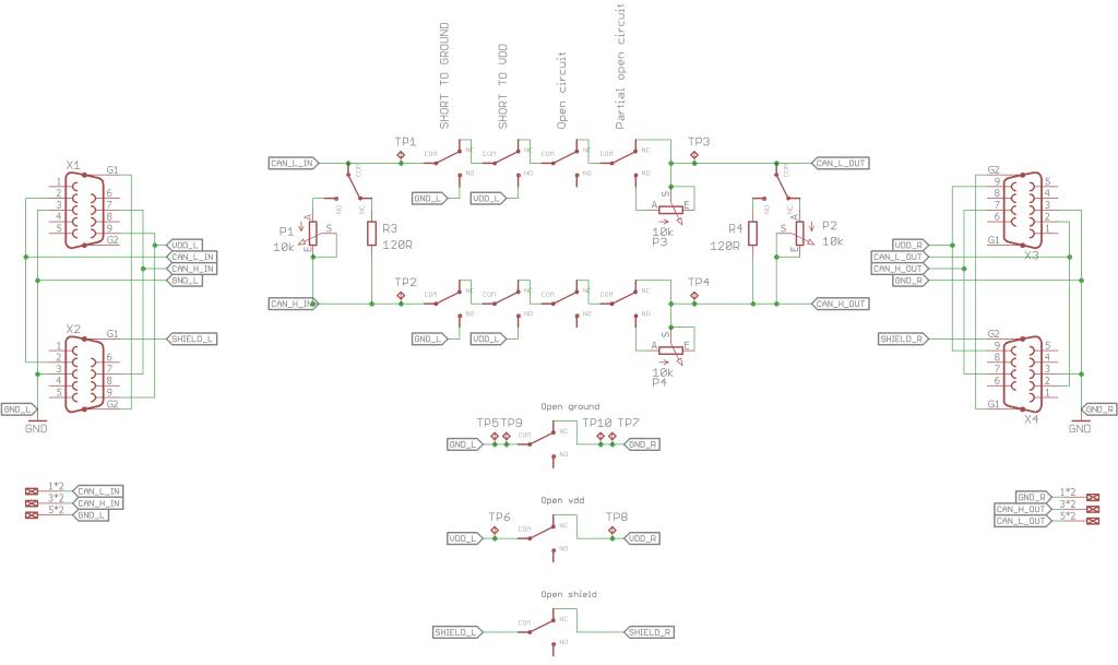
Possible to Inject Faults
- No fault (input and output D-SUB connectors connected without any error)
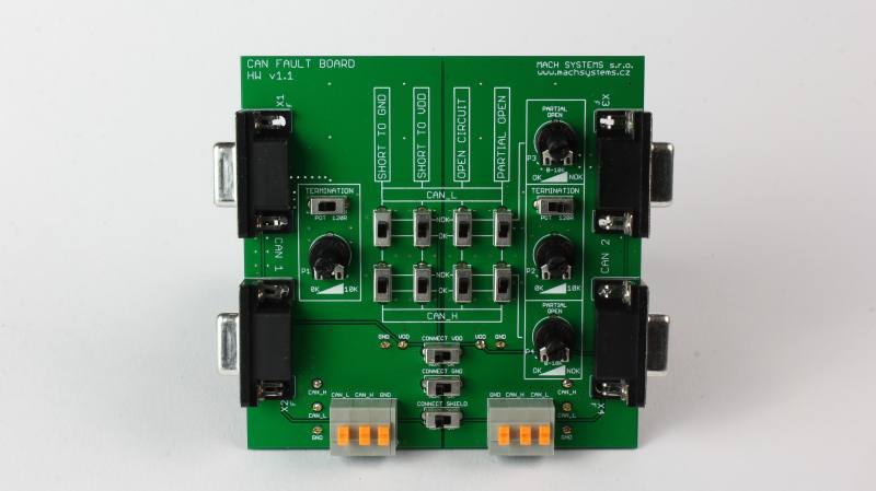
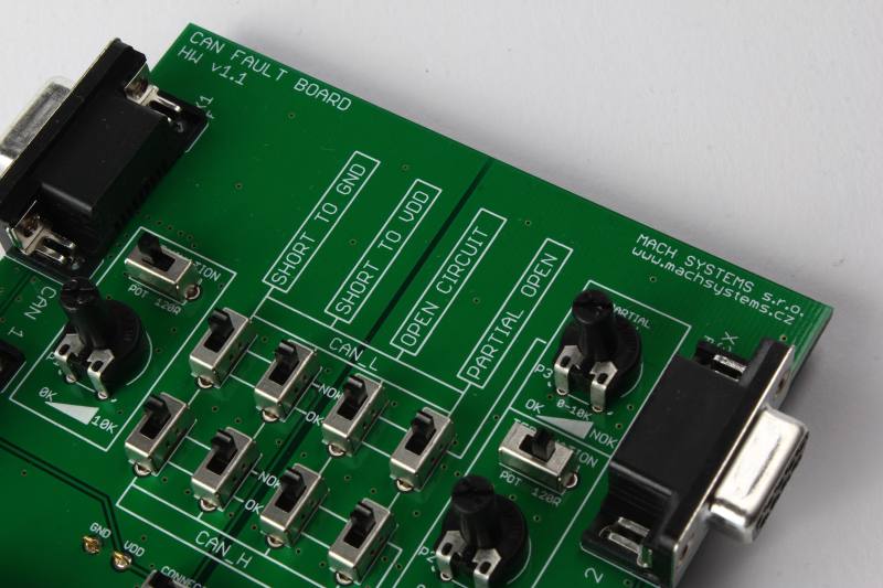
- Termination resistors (pins 2+7): the value can be changed (potentiometer 0-10 KOhm) / possibility to switch to a fixed 120 Ohm resistor
- CAN_L (pin 2): Short to GND, Short to Vdd, Open, Partially Open (potentiometer 0-10 KOhm)
- CAN_H (pin 7): Short to GND, Short to Vdd, Open, Partially Open (potentiometer 0-10 KOhm)
- CAN_L shorted to CAN_H (a termination resistor of 0 Ohm)
- GND open (pin 3)
- Vdd open (pin 9)
- Shield open (pin 5)
Technical Specification
- Input Connectors: 2x D-SUB9 F (wired 1:1)
- Output Connectors: 2x D-SUB9 F (wired 1:1)
- Terminals for connecting wires of an existing network
- Test points for an oscilloscope probe at important signals
- Compatible with CAN, CAN FD, FlexRay, RS-485, LIN
- 4x adhesive rubber pad at the bottom
- Dimensions 100 x 100 mm
Ordering Information
| P/N | Product | |
|
a PCB board for physical layer fault injection and simulation |